Diagnostics and Monitoring
Ultra Sonic Testing of rails
Rail Flaw detection systems of our OEM are designed to record internal flaws by Ultrasonic Testing method in the speed range from 0 to 140 km/h without compromising the reliability of testing. Innovative design of the equipment makes it possible to place it both on a standard bogie of most of the cars between wheel sets. Ultrasonic flaw detection system provides accurate positioning of the search systems relative to the rail top due to the interaction of the magnetic fields of the permanent magnets. The system uses transducers that emit ultrasonic waves with certain angles of rotation on working surfaces of the rail head, which leads to the absence of non-tested areas. The software is capable of presenting control data as per the requirements of any railways in the world. All received information is processed in real time, recorded and saved for further analysis and planning of works on the routine maintenance and repair of the track.
Key Features of the system
-
Operating speed up to 140 km/h.
-
Sliding probes ensure stable operation in all climatic conditions.
-
Simple design makes it easy to install and uninstall the acoustic unit and complete system.
-
Slight running time of ultrasonic waves in the acoustic unit protector provides a reliable testing in significant area of rail.
-
Unlimited passage of turnouts of any projects.
-
Design of the acoustic unit and the wide assortment of converters make it feasible to implement any scanning pattern to meets the requirements of flaws detection according to regulatory documents of various countries.
-
The use of water as a contact liquid and its direct supply to the acoustic units through the fittings ensures its minimal loses.
-
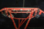
The design and installation of system are depicted in the photos shown below:


Rail Profile Inspection Systems
The full rail profile measurement system is designed to measure full rail profile in the speed range from 0 to 250 km/h. The system is installed on the frame of the car bogie. The system design is compact, light which makes it extremely easy to install and uninstall the entire system. Additional three-dimensional cameras that monitor the outside rail surface make it feasible to estimate rail wear and other additional parameters from an external inactive side.
Additional lasers provided to get a single line of exposure with the main lasers, increases the power and intensity of their illumination to the rail surfaces and successfully combat against possible exposure in sunny weather to obtain high-quality data under all weather conditions and also makes its reliable operation with "shiny" (wet, grinded, polished) rails.
Full rail profile monitoring system is capable for measurement of the equivalent conicity which ensures proper level of movement safety on high-speed sections of the railways. Specialized optical circuit of the system makes it possible to recognize the railway crossings and their elements. The camera's field of view makes it possible to perform an automated analysis of the track components e.g. rail joints, sleepers and bonds. Availability of monitoring from the outside makes it possible to perform reliable identification of defective bonds on the outer surface.
Software
All received information is processed in real time, recorded and documented for further analysis and planning of works on the routine maintenance and repair of the track. The software of the system makes it possible to compare information on the actual condition of the rails with data from the database of the track section. The principal and installation of system shown in following figures


Track Geometry Assessment Systems
The track geometry parameters assessment system fully complies with modern international standards. The contact system is capable to record up to a speed of 100 Kmph and non-contact system in a speed range of 0 to 250 km/h.
Contact system
It is a system of sensors placed on three or four measuring trolleys, which are mounted on the body and the frames of car bogies of the rolling unit. The parameters of track section are recorded and verified. The coordinates of kilometer posts, artificial structures, railway crossings, turnouts, etc. are also recorded
Noncontact system
It is mounted on the frame of car bogie of any rolling unit. It makes possible to receive accurate measurement data at speed range from 0 to 250 km/h. Such operating speed was reached by a combination of optical triangulation and inertial principle. The first method is used for contactless measurement of the position and geometry of both rail ways using illumination lasers and receiving video cameras as used in full rail profile measurement system, and the second method is based on the use of a inertial navigation platform system to automatically determine its rolling performance and orientation parameters in three-dimensional mode in real time using an inertial measurement unit.
Software
All received information is processed in real time, recorded and saved for further analysis and planning of works on the routine maintenance and repair of the track. The software of the system makes it possible to compare information on the actual condition of the rails with data from the database of the track section, to perform automatic comparison and generate reports and recommendations for managing and operating units of the railways.
The principal and mounting arrangement of system are shown in the photos shown below:


Video Inspection
The Video Inspection system performs the condition monitoring of the railway track components and infrastructure facilities in an automated mode and has capability to combine it with laser triangulation.
One of the main components of these systems is high-speed linear cameras, which are capable to record at high resolution of 1 mm/pixel at speeds up to 400 km/h.
Specially designed illumination system ensures the preservation of a clear and contrast image in all weather conditions and at any time of the day.
Powerful data recording and analysis system provides image compression without loss of quality in real time, increasing the autonomous time of work passes without archiving data up to 10000 km. The principle of operation of these systems is based on the visual detection of surface flaws of the rail using a linear video camera. The rays of light reflected from rails pass through the lens of the video camera and hit the matrix. The resulting image is digitized and transmitted via a high-speed interface to the server, where data is recorded for later decryption.
The system is capable to monitor 64 types of flaws, which includes cracks, rail sagging, condition of track bonds, bridge plates and bolts, rail shelling, damage to welded joints, presence of ladder treads in the joints and stagger of rail joints, damage to the sleepers, etc., in real time and post-processing modes. The system is capable to operate in all seasons of the year in the temperature range from -50 °C to + 45 °C. Detail of system components and their mounting arrangements are shown in figures


Clearance Envelope Inspection Systems
Clearance envelops Inspection system scans in three-dimensional for monitoring the condition of tunnels, analysis of the parameters of the ballast section and verification of the obstruction and rolling stock clearance. The option to choose speed and high-speed scanning system are available.
Speed scanning system
Specially designed for severe operating conditions, the system makes it possible to perform during all weather conditions prevalent round the year for measurement of infrastructure facilities at speeds up to 140 km/h with a measurements step not exceeding 200 mm. The system is based on a laser scanner operating on the principle of phase shift measurement. The high accuracy and quality of the equipment design make it possible to achieve a minimum measurement error throughout the operating range.
High-speed scanning system
Designed for monitoring at high speeds, the system combines from 1 to 6 high-speed laser scanners with various cameras to achieve high image resolution with impressive results with a measurement step of 50 mm at speeds up to 320 km/h.
Software:
The unique software has the innovative filtering and compression system to use only the information actually necessary.
The program modules are capable for data analysis and reporting necessary for effective infrastructure management. The software has following capabilities
-
Two-dimensional and three-dimensional display of the measured area with the overlay of the video of the specified clearance violations.
-
measured rolling stock clearance;
-
Determination of deviations in the content of the ballast section.
-
Two-dimensional and three-dimensional display of tunnels with automatic detection of wall defects;
-
Position of the overhead line;
-
Report on sites with violence of clearance;
-
Report on the condition of the tunnel;
-
Report on the condition of the ballast section;
-
General report on the site condition.
A typical design of clearance envelops measurement adopted for adopted for Indian Railway is shown in photo below:


Overhead Line Inspection
One of the most effective devices of this type is a complex of automated monitoring of the parameters of the overhead line. It is placed in a diagnostic car, on the roof of which (above the axis of the car bogie) a measuring current collector and an observation tower with measuring equipment are installed. In addition to determination of the type and voltage magnitude of the overhead line, special devices of the complex measure and record limit-exceeding deviations of the parameters of all its facilities and on the basis of this data automatically calculate a scoring of its technical condition at the inspected track section. Design of the observation tower provides an overview of the control and measurement systems of video inspection, thermal monitoring and UV diagnostics, installed on the tower.
High-speed overhead line control systems
All the measurements of the overhead line and pantograph are performed by sensors using noncontact method, and the recorded signals are processed by the information and computer system of the complex.
Parameters of the overhead line are measured in height above the level of the rail top and line position (zigzag and offset) in the section, with the number of wires from one to eight. Simultaneously, the equipment monitors lowering of the aerial frogs and the height of the locks relative to the line, measures the pulling force of the pantograph on the overhead line and records its impacts on pantograph, pressing the overhead line and detaching it from it.
The processed measurement results, including recorded deviations from the standard line parameters, are displayed in real time in the form of charts on the computer monitor of the operator's workstation and are archived on the hard disk or removable media. Results of thermal diagnostics, as well as UV camera data are recorded into separate files. In this, all data are linked to the readings of the sensor of speed and the traveled distance, as well as to the registration points of the overhead line. It is possible to print the charts.
Key Features
-
No moving parts inside the measuring system. All components operate in a static position. This makes it possible to achieve accuracy and eliminates the need for frequent system calibrations.
-
Measurements are not affected by sun influence, thus it feasible to perform measurements even in daylight.
-
The system is capable of making up to 5000 measurements per second, this makes it feasible to detect wear of catenary wire.
-
No part located in close proximity to high-voltage components. This increases the system security.
-
The service life of laser based system is much greater in comparison to conventional lamp based systems.